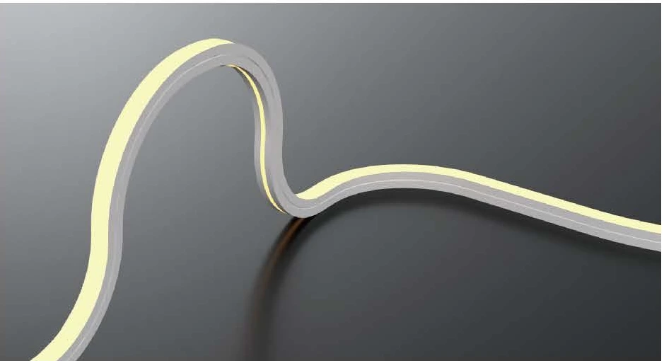
Free-Bending LED Neon Flex
MODELS
NF01010 · NF01616 · NF02020R · NF05025
10–25 W/mWhite configurations
10 × 10 mm / 16 × 16 mm / 20 × 20 mm (rounded) / 50 × 25 mm
Four profiles for multi-directional architectural curves
View Product & Specifications
Compare free-bending, top-bend, side-bend and three-side emitting LED neon flex. Explore 11 models across four product groups, with profile dimensions, bend limits and cable exits matched to the architectural detail.
Architectural Neon Flex
Follow changes in an architectural line with free-bending LED neon flex. Compare compact square, rounded and wide profiles, then match the minimum radius, light configuration and cable exit to the proposed route.
Free-Bending Product Group
4 models
MODELS
NF01010 · NF01616 · NF02020R · NF05025
10–25 W/mWhite configurations
10 × 10 mm / 16 × 16 mm / 20 × 20 mm (rounded) / 50 × 25 mm
Four profiles for multi-directional architectural curves
View Product & SpecificationsArchitectural Neon Flex
Choose top-bend LED neon flex when the installation follows the bending plane shown in the model drawing. Compare a 6 × 6 mm profile, an 11 × 8.8 mm semicircular section and a 20 × 20 mm square section for the space available.
Top-Bend Product Group
3 models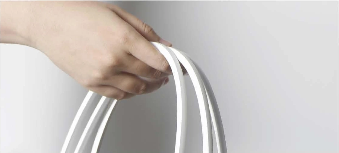
MODELS
NF0606 · NF1108 · NF2020
8–14 W/mWhite configurations
6 × 6 mm / 11 × 8.8 mm (semicircular) / 20 × 20 mm
Compact, semicircular and square profiles for top-bending paths
View Product & SpecificationsArchitectural Neon Flex
Plan curved outlines in the side-bending plane with NFA-series LED neon flex. Choose a narrow 4 × 10 mm section, a 10 × 10 mm square profile or a taller 10 × 20 mm section, using the actual bend and fixing details to guide selection.
Side-Bend Product Group
3 models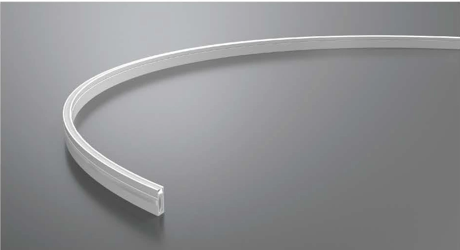
MODELS
NFA0410 · NFA1010 · NFA1020
8–14 W/mWhite configurations
4 × 10 mm / 10 × 10 mm / 10 × 20 mm
Three cross-sections for side-bending architectural lines
View Product & SpecificationsArchitectural Neon Flex
NF03025R uses a three-side emitting profile for architectural details where the illuminated surface remains visible from more than one side. Review the original product view and rounded 30 × 25 mm section before planning an exposed line of light.
Three-Side Emitting Product Group
1 model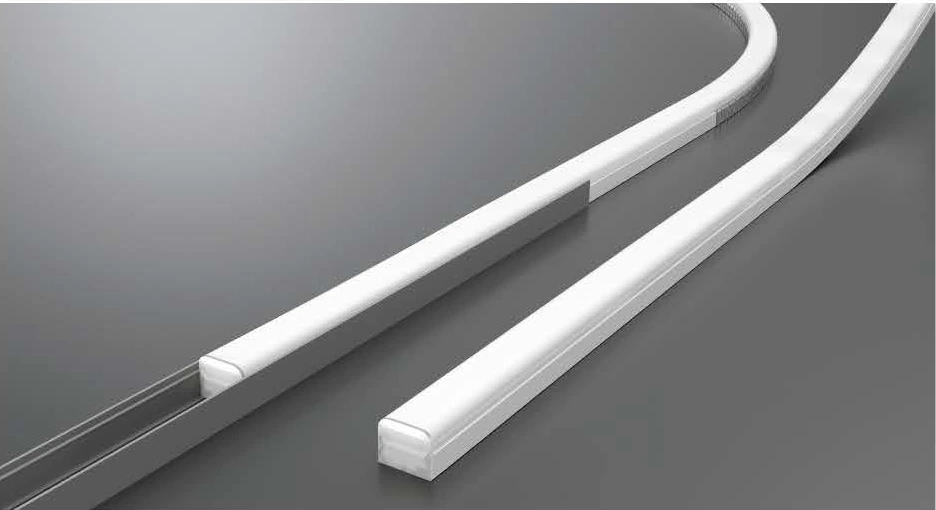
MODELS
NF03025R
25 W/mWhite configurations
30 × 25 mm (rounded)
NF03025R · a 30 × 25 mm multi-face luminous profile
View Product & SpecificationsProduct Categories
Browse CRANE’s core architectural lighting categories for facade, exterior and landscape lighting applications.
Linear wall washing for facades, exterior walls and architectural surfaces.
Explore Category →Powerful exterior illumination for facades, structures and landscape projects.
Explore Category →Continuous linear lighting for architectural outlines, facade details and exterior structures.
Explore Category →Dynamic point-source lighting for media facades, outlines and architectural effects.
Explore Category →Flexible linear lighting for coves, outlines and outdoor architectural details.
Recessed exterior lighting for facades, pathways, landscapes and architectural accents.
Explore Category →APPLICATIONS
Review the bending plane and radius along a canopy, feature edge or curved architectural line.
Coordinate the profile, channel and cable exit with the recess. Leave access for connections and maintenance.
Use the NF03025R product view to review a detail where more than one emitting face is intended to remain visible.
SELECTION GUIDE
Compare the actual cross-section and its fixing accessory. The 6 × 6 mm NF0606, 4 × 10 mm NFA0410 and 50 × 25 mm NF05025 serve very different installation details.
Match the permitted bend plane and minimum radius to the drawn curve. Reserve space for the cable exit shown for the exact model.
Use the selected white or colour configuration for power and cut-length planning. A maximum connection run is not a roll length; coordinate separate feeds where needed.
FAQ
Start with the required bending plane, then check the model-specific minimum radius. Use the original direction diagram to orient the emitting face correctly. Similar profile dimensions do not make the bending structures interchangeable.
Neon flex can create visible linear or curved architectural outlines where the selected profile, bending plane and mounting arrangement suit the design. Evaluate the emitting face and actual viewing direction as well as the supporting surface.
Consider it when the route requires the bending planes supported by the chosen free-bending model. Check the model diagram, minimum radius, fixing and any torsion limits; the name does not mean unrestricted twisting or infinitely tight curves.
Use the drawing and limits for the exact model and bending plane. Distinguish radius from diameter, and check the finished route and fixing method; similar-looking sections need not share the same limit.
Only at the approved cut units for the selected model and light configuration, using the specified termination procedure. Confirm the actual orderable length and cutting conditions; the units can differ across products and configurations.
Use the manufacturer’s limit for the exact voltage, model and light configuration, then design supply feeds and cable sizing for the project. A reel or architectural route length is not automatically a permitted single-feed length.
Select the model for the site exposure and follow the approved cable, end-cap and sealing instructions. The factory IP rating does not automatically establish the rating of a field-cut or connected assembly; verify the completed installation.
Provide the route and curve geometry, selected profile or available section, light color and control, powered segment lengths, supply locations, cable exits, mounting and exposure. Request the model-specific bending, cutting and connection instructions.
START A PROJECT
Share the curve, installation section, run lengths and light requirements. Our team will review the applicable model and configuration with you.